Processing of Micro tool coating

To the cobalt treatment, the need to selectively etching out the most appropriate amount of cobalt, and not too much to weaken itself is very thin micro-cutting tool In order to prevent the removal of too much drilling and affect the integrity of the tool, Weight ratio) must not exceed 6% to 8%. “We cut all the cobalt in the thin surface to prevent it from affecting the growth of the diamond,” says Pfefferkorn, “and we minimize the effect of tool integrity by controlling the depth of the etch.”

The paper points out that the research team at the University of Wisconsin-Madison conducted a seeding operation after completion of the etching: the use of ultrasonic treatment in acetone, the use of nano-diamond powder on the matrix deposition of diamond particles. The introduction of the grain played a role in positioning, where the diamond began to grow (ie nucleation). Nano-diamond powder agglomeration leads to uneven seeding and uneven growth of diamonds. Therefore, the researchers used ultrasonic cleaning in alcohol solutions to ensure that large grains were removed to achieve uniform seeding.

Then, using the hot-wire chemical vapor deposition system designed and fabricated by the research team, nano-grain and fine-grained diamond were grown on the tool. Carpick confirmed that the grain size of nanocrystalline diamond was 10 to 100 μm, Particle size greater than 100nm, less than 300nm). The deposition system comprises a deposition chamber in which the tungsten wire at a temperature of at least 1800 ° C is filled with a shielding gas (particularly methane diluted in hydrogen).

The thickness of the coating obtained by deposition is about 60 to 200 m. The average tool has a diamond coating thickness of 2μm or more, which is too thick for micro-tools because the radius of the cut edge of the uncoated micro-tool is often less than 1μm. “The thickness of the coating used for large-scale tools is not suitable for micro-tools, it will passivate the tool and thus greatly reduce its cutting performance,” Carpick said.
Find a better micro-tool coating

Since the coating of the cutting tool is beneficial to the processing of the macro size, there may be reason to deduce that the tool coating is also advantageous for small size machining. If the coating is properly applied and the coating thickness is thin enough to pass the microcrystalline edge, some researchers may agree with this view. However, these researchers have not yet finalized whether the micro-tool coating is conducive to processing, as well as the best way to coat.

In order to understand how to more effectively the micro-tool coating, some universities are carrying out relevant research. This paper is a study of the University, including the deposition of diamonds and other coatings on micro-tools, the selection of preferred coating methods, and the study of different workpiece materials on the coating tool response.

Application of an increasing number of diamond coatings

One of the challenges for diamond coatings is the adhesion of the coating to the tool surface. A team of researchers from the University of Wisconsin-Madison, the University of Pennsylvania and the Argonne National Laboratory has deposited a layer of transition on micro-end mills to enhance the adhesion of diamonds, And deionized water were tested on a 300 μm double-slot micro-end mill. According to Flank E. Pfefferkorn, assistant professor of mechanical engineering at the University of Wisconsin-Madison, one of the purposes of this test is to create a mechanical link between the cemented carbide substrate and the diamond coating.

Pfefferkorn and Robert W. Carpick, Associate Professor, Department of Mechanical Engineering and Applied Mechanics, University of Pennsylvania (who was dedicated to the study of diamond coatings at the University of Wisconsin-Madison) and his graduate students and partners in the paper titled “Diamond Micro Milling cutter: the ability to micro-size aluminum cutting “papers pointed out that the cobalt binder can enhance the toughness of the tool, but will weaken the diamond coating and the bonding strength between the matrix, and by limiting the formation of nuclei and inhibit the diamond Grow. “The main reason for removing the drill from the surface of the substrate is that it hinders the growth of the diamond,” Pfefferkorn said.

Milling of graphite materials

When cutting graphite material, its high abrasiveness will make the standard carbide cutting tool rapid wear, and wear the tool will not be able to accurately cut out the required complex geometric shape. When milling graphite, the tool path and milling method are not the most critical factors, and the type of milling cutter usually depends on the shape of the graphite electrode. As the diamond-coated cutter has excellent wear resistance, it is widely used in graphite milling. Diamond grown on a carbide tool base creates a wear-resistant coating that is extremely high in hardness and can significantly extend tool life. The life of the diamond-coated tool is 10-30 times longer than that of the uncoated carbide tool.

For example, when a complex graphite electrode of 152.4 mm square is machined with an uncoated carbide ball milling cutter with a diameter of 12.7 mm, the sharp edge and detail features of the milling cutter are usually about 4 hours after milling Began to peel off. And a diamond-coated cutter can be more than 98 hours of continuous milling, the cutting edge will not occur peeling off.

The sharpness of the cutting edge of the milling cutter is particularly high when machining certain graphite workpiece shapes (eg thin ribs), sharp geometric profiles and small size workpieces. In such processing, the use of 2-3μm thick diamond coating can extend the tool life and keep the edge sharp. Because of this relatively thin diamond coating cost is low, it is very suitable for the tool life requirements are not too high low-end processing. While the typical thickness of 18μm diamond coating is mainly used for high tool life requirements of high-end processing.

The use of thinner diamond coatings makes it impossible for moldmakers who produce smaller batches and want to reduce tool costs without sacrificing tool life in order to reduce costs. They can still play a real diamond-coated carbide cutting tool performance advantages while at the same time using thinner diamond coatings to meet their specific processing needs. Today’s diamond coating thickness range is roughly 2-25μm.

The optimum tool for a particular process should depend not only on the material being cut but also on the type of cutting used and the milling method used. By optimizing the tool, cutting speed, feedrate and machining programming skills, you can produce parts faster and better at lower processing costs.

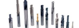
High performance drill bit from Calloytool

The engineering company says its replacement t-a rig system can significantly reduce downtime compared to solid tools. The t-a drilling system has high performance insertion and application for making engine block, crankshaft, piston and suspension parts. The cost of using the t-a drilling system is 25-50% lower than other options on the market.

It is reported that in the case of t – a drill line, every time the operator insert bit, will have a perfect factory or drill point on the ground, without stopping, for regrinding operation need to change the tool offset. These alternate techniques are consistent each time, unlike the changes that are often encountered when using different mechanics to drill ground.

The allied forces provide the cast iron (-ci) geometry for its t-a drill, which is an ideal choice for automotive applications. With a lower rake Angle and a harder cutting edge to make it more elastic, (-ci) bit is a good choice made of cast iron and head. You can also use training techniques for other specific applications. The Allies developed custom configurations for tools, including a special shape end at the end of the crankshaft.

The innovative coating for the t-a rig includes the exclusive WD200 coating of the allied forces, which improves performance and extends the service life of the cutter. A variety of insertion levels applicable to automotive applications, including carbonized carbide, a wear-resistant carbonized carbon and carbohydrate, is a good choice for aluminum and other nonferrous metals.

Steel applications using the CAN2 t-a drill can use the C1 option, which is the same as the original t-a, providing better performance and longer tool life for automotive applications.

The company has expanded its SAF replacement headdrill production line, including 12XD bit. The SAF’s replaceable head drill reportedly allows for deep excavation at a lower cost, as SAF users can purchase only one drill to reach the size of 5.

It adopts the original radial saw tooth joint design, SAF bit, or cutting edge, which is designed for high precision and stable drilling. Polished flute ensures good chip evacuation.

According to the company, SAF’s nickel-plated fuselage has a longer life span than a conventional removable drill. Hard alloy matrix with patented hard alloy coating has excellent wear resistance on cutting edge. A rigid saw tooth coupling system is used to fix the replaceable carbide tip on the drill bit, improving the precision and repeatability of the drill.

Sumitomo provides a series of drills to improve the performance of various materials. SAFT – MTL type bit is excellent in steel application, while SAFT -c has a chamfer edge to eliminate fracture in cast iron application. SAFT – MEL machine superalloy, stainless steel and cast iron processing power.

In addition to the new 12XD, sumitomo’s SAF line also includes 3XD, 5XD and 8XD replaceable hard alloy bits.

Selection of Milling Cutters under Complicated Machining Conditions-Milling straight wall

Milling straight wall

The use of bovine nose mills is best when milling a flat area with flat ribs or straight walls. 4-6 blade of the nose and nose cutter is particularly good at the straight wall with the external shape or very open parts of the copy copy. The greater the number of blades, the greater the feedrate. However, the machining programmer still needs to minimize the surface contact of the tool with the workpiece and use a smaller radial width. When machining on a less rigid machine, it is advantageous to use a smaller diameter cutter because the small diameter milling cutter reduces contact with the surface of the workpiece.

The use of multi-edged nose nose cutter (including walking step and cutting depth) is the same as the ring cutter. They can be used to cut the hardened material with a cycloid tool path (or a new tool path that can control the knife’s knife angle). As mentioned earlier, the most important thing is to ensure that the cutter diameter is about 50% of the groove width, so that the milling cutter has enough moving space and to ensure that the knife angle does not increase and produce excessive cutting heat.

Precision drilling of silver and diamond

The company‘s general drilling line includes precision drilling for precision drilling of silver and diamond. These decompression drills provide versatility and reliability.

The precision drill A56 is an inch diameter round handle suitable for an inch – in – holder bit. Regular flutes and total length allow minimum adjustment of drilling machine. Suitable for low – to moderate tensile strength of various materials.

The precision twist drill A57 features three planes with a diameter of an inch and a corrected anti-skid.

Precision twist drill A56CO is produced by high quality cobalt steel for improving hardness, abrasion resistance and thermal resistance. It is characterized by a 118 a self-centering locations, accurate positioning and easier to insert A56CO is an ideal material of tensile strength of high strength, can produce high cutting temperature, such as high alloy steel, iron castings, stainless steel and other hard processing material.

WE cutting tool company carbide tool set of the introduction of the new “rapid drilling” geometry, according to the report, which provides unprecedented cutting speed and tool life than ever, including grey cast iron, nodular cast iron and forging steel, these are the popularity of automotive engine and chassis components material. With a new round radius design, it has nothing to do with the Angle of the drill, but it has nothing to do with the diameter. These verified designs solve the challenging, high-yielding drilling applications. Tool selection includes standard drill and endmill procedures for all materials groups; Special tools include step drilling, coring, reamer, taper drill, tapered reamer and assembly tools (drilling and milling), and provide superior cost/performance ratio.

In decades of experience and engineering, Calloy tools provide a single tool for drilling operations, providing solutions for project management of all solid carbide tools. The precision and precision are ensured by industry-leading innovative design, ultra-modern CNC grinder and strict iso 9001 quality system.

Calloy’s sales and application engineers can assist with the selection and design of tools to meet specific application requirements with the best geometry, the latest carbonization grade and advanced coatings. Fast and reliable delivery time, with decades of experience in the design and manufacture of precision hole tools.

Complicated machining process-Milling small parts

Milling small parts

A circular milling cutter is the best choice for milling small parts (such as helical milling and milling ribs, or when the cutter diameter is close to the workpiece radius). The solid ring shape of this cutter can produce a chip thinning effect that allows it to be milled at a higher feed rate. In addition, the radius of the milling cutter is smaller than that of the conventional ball end mill, so it can increase the walking step, while still maintaining the flatness of the machined surface without the usual occurrence of the ball milling cutter Large knife marks.

The ring cutter is ideal for helical milling and milling ribs because the tool will inevitably produce more contact with the machined surface, while the use of double-edged circular milling cutters minimizes contact with the surface of the workpiece, Thereby reducing cutting heat and tool deformation. In these two machining, the circular milling cutter is usually closed in the cutting state, so the maximum radial walking step should be 25% of the diameter of the milling cutter, and each time the maximum Z direction of the knife should be cut 2% of diameter. In the helical milling hole, when the cutter is cut into the workpiece with the helical cutter rail, the spiral cutting angle is 2 ° – 3 ° until the Z direction of the cutter diameter is 2%.

If the ring cutter is open in the open state (such as milling the workpiece corner or cleaning the workpiece characteristics), the radial walking step depends on the hardness of the workpiece material. When the hardness of the workpiece is HRC30-50, the maximum radial walking step should be 5% of the diameter of the cutter; when the material hardness is higher than HRC50, the maximum radial walking step and the maximum Z The depth of cut is 2% of the diameter of the cutter.

Freze Kesicilerinin Seçimi – Komple işleme işlemi

Makine sertliği, kullanılabilen aracın boyutunu belirlemeye de yardımcı olur. Örneğin, 40 konik makinede kesim yaparken, freze bıçağı çapı normal olarak <12.7 mm olmalıdır. Daha büyük çaplı frezeleme aletleri, makinenin dayanma kabiliyetini aşan daha büyük kesme kuvveti üretebilir; bu da çarpma, deformasyon, yüzey bitirme bozulması ve takım ömrünün kısalmasına neden olur.

Buna ek olarak, parçanın en küçük çapının öğütme frezesinin 1/2’inin kullanılması, küçük bir bıçak bıçağı açısı tutabilir ve direksiyon sırasında takım artmaz. Örneğin, iş parçası işleme programı% 10’luk bir yürüme adımı, daha sonra bıçak açısı 37 °’yi kullanır. Eski, geleneksel alet yolunu kullanırsanız, yön değiştirdiğinizde kesici açısını 127 ° ‘ye değiştirecektir. Ve yeni yüksek hızlı takım yolunun kullanılması, sesin köşesinde kesici ve düz çizgi kesme işlemi farklı değil. Bir kesiciye tüm kesme işlemlerinde aynı ses verilirse, büyük bir termal şoka ve mekanik darbeye maruz kalmadığına işaret eder. Kesici her turda çığlık atıyorsa veya bir köşede kesilirse, bıçağın açısını azaltmak için kesicinin boyutunu azaltmanın gerekli olabileceğini gösterir. Kesimden çıkan ses aynı kalırsa, bıçağın açısı daima sabit olduğu için, kesicinin kesme basıncının üniform olduğu ve iş parçasının geometrisinin değişmesi ile yukarı ve aşağı dalgalanmadığını gösterir.

Selección de fresas en condiciones de mecanizado complicadas-Ruta de herramienta de alta velocidad

En el proceso de corte, con el fin de maximizar la calidad de procesamiento y la repetibilidad, es necesario seleccionar correctamente y determinar la herramienta adecuada, lo que es especialmente importante para algunos difíciles y difíciles de procesamiento. Este documento proporciona algunos principios rectores para seleccionar una fresa en algunas condiciones difíciles de procesamiento (por ejemplo, trayectoria de alta velocidad de la herramienta, pequeña parte del fresado, pared recta y pieza de trabajo de grafito).

Ruta de la herramienta de alta velocidad

Los sistemas CAD / CAM actuales pueden ser controlados controlando con precisión la longitud de la cuchilla en la trayectoria de cicloide de alta velocidad (observe que la trayectoria de cicloide es una trayectoria curvada formada por un punto fijo a lo largo de una línea recta). Incluso cuando el cortador corte en la esquina u otras formas geométricas complejas, el cuchillo no aumentará la cantidad de cuchillo. Con el fin de aprovechar al máximo este avance tecnológico, los fabricantes de herramientas han diseñado y desarrollado molinos avanzados de pequeño diámetro. Las fresas de diámetro pequeño son menos caras que las fresas de mayor diámetro, y con frecuencia se pueden extraer más piezas de trabajo por unidad de tiempo utilizando trayectorias de herramienta de alta velocidad. Esto se debe a que la fresa de gran diámetro y la superficie de contacto de la pieza de trabajo son mayores, por lo que es necesario reducir la velocidad de alimentación, utilizando una velocidad de alimentación más tradicional. Por lo tanto, el cortador de diámetro pequeño puede obtener una mayor tasa de eliminación de metal.

Sin embargo, los diseñadores de herramientas todavía necesitan asegurarse de que estas fresas de pequeño diámetro no sólo son adecuadas para el corte cicloidal, sino también con el material de la pieza a mecanizar para que coincida. Hoy en día, las formas geométricas de muchas herramientas altamente eficientes están específicamente diseñadas para materiales procesados ​​específicos y la tecnología de corte utilizada. Por ejemplo, con una trayectoria de herramienta optimizada, se puede utilizar un cortador de 6 cuchillas para moler la ranura completa en acero H13 con una dureza de HRC54. Con un diámetro de 12.7mm cortador se puede cortar el ancho de 25.4mm ranura. Si se mecaniza una ranura de 12,7 mm de diámetro con un diámetro de 12,7 mm, la herramienta tendrá contacto superficial excesivo con la pieza de trabajo y hará que la herramienta falle rápidamente. Una regla general útil es usar una fresa con un diámetro de aproximadamente 1/2 de la parte más estrecha de la pieza de trabajo. En este ejemplo, la parte más estrecha de la pieza de trabajo es una ranura con una anchura de 25,4 mm. Por lo tanto, el diámetro máximo de la fresa utilizada no debe exceder los 12,7 mm. Cuando el radio del cortador es menor que la parte más estrecha del tamaño de la pieza, la herramienta tiene un espacio de movimiento izquierdo y derecho, y puede obtener el ángulo mínimo del cuchillo. Esto significa que la fresa puede utilizar más bordes de corte y velocidades de alimentación más altas.

Alloy milling cutter-the ways to reduce wear and tear

Alloy milling cutter in the course of more or less will encounter damage or wear and the like, but sometimes it is inevitable. However, we can do our best to minimize the damage. What are the ways to reduce wear and tear.

Needless to say, in the milling of nickel-based alloy, the heat is the most important factor affecting the life of the tool, even if the best carbide cutting tools, will be too high cutting heat destroyed. Resulting in a very high cutting heat, not just the problem of milling nickel alloy. So the need to control the heat when milling these alloys. In addition, it is also important to understand the amount of heat generated when machining various forms of tool (high speed steel tool, carbide cutting tool or ceramic tool).

Many of the tool damage is also related to other factors, different grid fixtures and tool holders are likely to shorten the tool life. When the clamping of the workpiece rigidity, cutting movement occurs, may cause the carbide matrix fracture. Sometimes produce small cracks along the cutting edge, and sometimes from the carbide blade collapse of a piece, can not continue to cut. Of course, this chipping may also be due to the hard alloy is too hard or cutting load caused by too much. At this time should consider the use of high-speed steel cutting tools to reduce the occurrence of chipping. Of course, high-speed steel tools can not be as hard alloy as the higher heat. What kind of material should be used, must be determined according to the specific situation.

Before the start of the process, the idea of strengthening the rigidity of the fixture, the future long-term production will bring benefits. Not only to extend the life of the tool, but also improve the workpiece surface quality, reducing the processing error.

Similarly, improper selection of the handle, but also shorten the tool life. Such as the diameter of 3.175mm end mill installed in the cutter handle (rather than the spring chuck), due to the role of fastening screws, so that the tool and the handle between the gap between the side, the tool center deviation The tool holder rotates the center so that the radial runout of the milling cutter increases, resulting in uneven cutting of the cutting load of each cutter. This cutting state is detrimental to the tool, especially when milling nickel-based alloys.

By using a tool holder that improves the eccentricity of the tool loading card, such as a hydraulic chuck and a hot chuck, the cutting effect can be more balanced and smoother, reducing tool wear and improving the surface quality. Select the knife handle should follow a principle, that is, the handle to be as short as possible. These clamping requirements for tools and workpieces are applicable to milling any material, and when milling nickel-based alloys, advanced machining experience is required.